Home
About
Contact

My 3D Printer
  ⇒ Plans & BOM 3D Printed Kayak
  ⇒ Plans & BOM My Fab@Home     ⇒ Plans & BOM

 As seen on:


RSS Feed

My 3D Printer

Picture of the printer circa June 2013. The printer has been upgraded to have a heater build chamber in order to print soild ABS plastic parts with no qarping or cracking.

Picture of the largest section of the kayak, section 15, on the build plate, with the door of the heated chamber removed.

Picture inside the build chamber during printing

A more recent picture of the machine circa August 2011. There have been many modifications since the last image (above) including a higher resolution print head, build surfaces and control electronics.

3D printer of my own design, that I have been working on since late 2008 and is now fully functional as of Summer 2010. It prints parts in ABS plastic with a maximum build area of 403.00 x 403.00 x 322.70 mm [15.86 x 15.86 x 12.70 inches].

The build base moves in the X and Y planes, while the tool moves only in the Z plane.

The build base allows for different surfaces to be attached and is heated. Here is a polyimide film coated surface, suitable for ABS plastic printing. This has since been changed to PET film as it is much more durable for ABS plastic printing.

The old plastic extrusion tool takes in a feedstock of 3mm ABS plastic filament. The filament is compressed between a servo motor driven knurled pulley and an idler wheel. The filament is then forced down through a 0.50mm nozzle heated to 220°C.

The old plastic extrusion tool [left] next to the New extrusion tool [right]. The new extruder takes in a feedstock of 1.75mm ABS plastic filament. The filament is compressed between a stepper motor with a planetary gearbox which drives fine toothed gear and a spring loaded idler wheel. The filament is then forced down through a 0.35mm nozzle heated to 220°C. This new extruder is about a quarter the size of the old extruder and also effectively doubles the resolution of the the machine. (Note: New extruder is shown without nozzle/heater portion attached)

The extruder controller board [left] provides power to the nichrome wire heated extruder barrel and nozzle using PID control. A magnetic rotary encoder [right] provides closed loop feedback on the drive motor for accurate extrusion.

The two beige parts here were printed on the machine itself. One is a mount for the magnetic rotary encoder [left] and the other is the nozzle for the fume extraction system [right] which is connected to the blue hose.

The brass nozzle and heater barrel [bottom left] are covered with ceramic insulation for better temperature control. This heated portion is then itself insulated from the plastic tool housing via a PEEK tube. Fume extraction nozzle is on the right.

Side view of the machine.

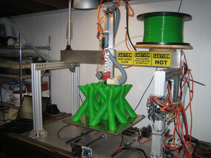
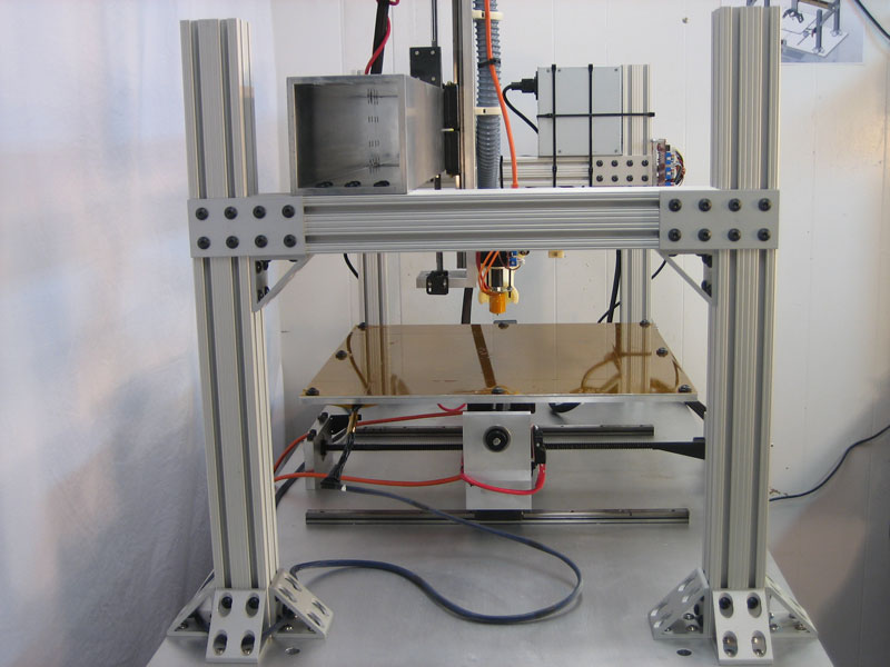
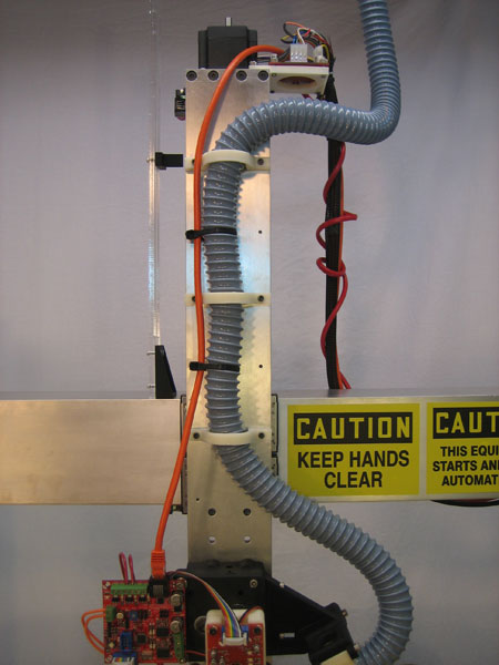
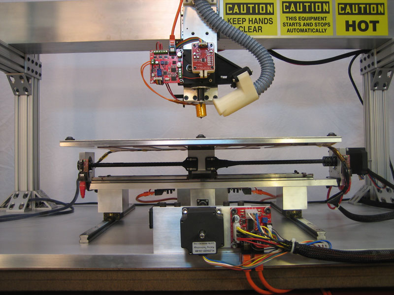
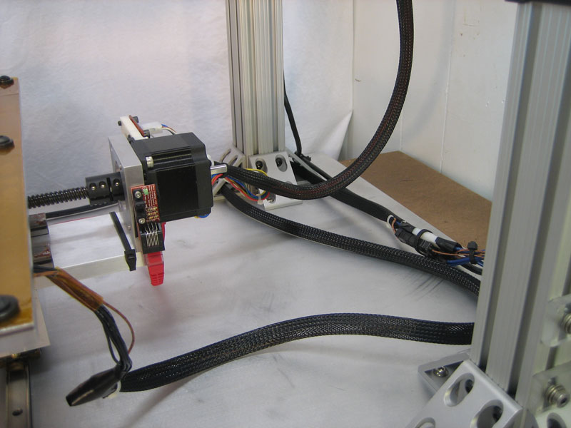
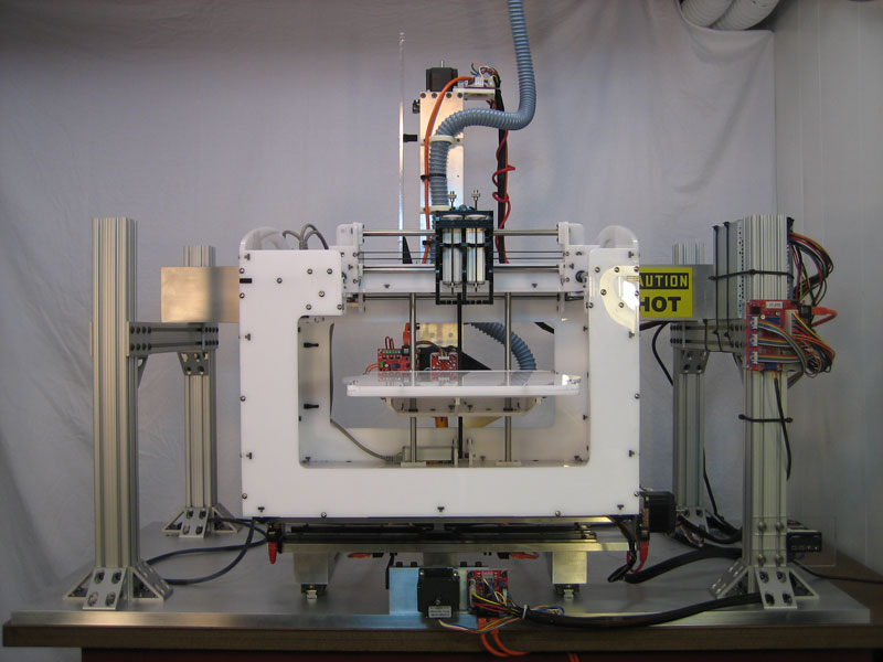
80/20 extrusion is used to support the Z axis. This is so the height of the Z axis can be varied depending on the tool and task. For example, if a rotary cutting tool head is attached to cut wood, the Z axis would ideally need to be located as close to the cutting surface as possible to reduce the moment on the axis.

View of the Z axis. Brackets holding in the blue hose in place were printed on the machine itself. On the left is an adjustable optical end stop flag. All axes have adjustable optical end stops to prevent damage.

Side view of the XY table. All axes are actuated by stepper motor driven ACME lead screws with anti-backlash nuts. All axes move on caged linear ball bearings guides.

Underside of the build base with orange heaters and thermocouple. During ABS plastic printing the base is kept to a consistent 112°C.

Bipolar stepper motor with the driver board [right] mounted on bracket printed on the machine itself.

RJ45 cable is used to connect the optical end stops to the stepper driver boards.

Cable management.

Microcontroller interprets Gcode commands.

PID temperature controller for the heated build base.

Some of the first parts that have been printed on the machine with the old extruder. [left] A two way hose splitter for the fume extraction system. [center] Human head from CAT scan data. [right] Vent adapter for an air conditioning system on a 1968 Camaro.

Fume extraction system based on old dual blower fan. [4x] adapters (white/beige parts) were printed for the fan on the machine. White hoses lead to the outside while blue hose come from the machine. The two way hose splitter part from the previous image combines the suction from both blower fans to reduce fumes.

A Fab@Home Model 2.0 [fabathome.org] sits on the build base of the machine for a scale comparison.

© 2024 GrassRootsEngineering.com