
NOTE: While Face Shields are important PPE, Increasing the usable life of currently existing N95 respirators is one of the very highest priorities and will be the focus of my subsequent posts.
Update 04/01/2020: I have added a top shield piece, see details at the end of the post.
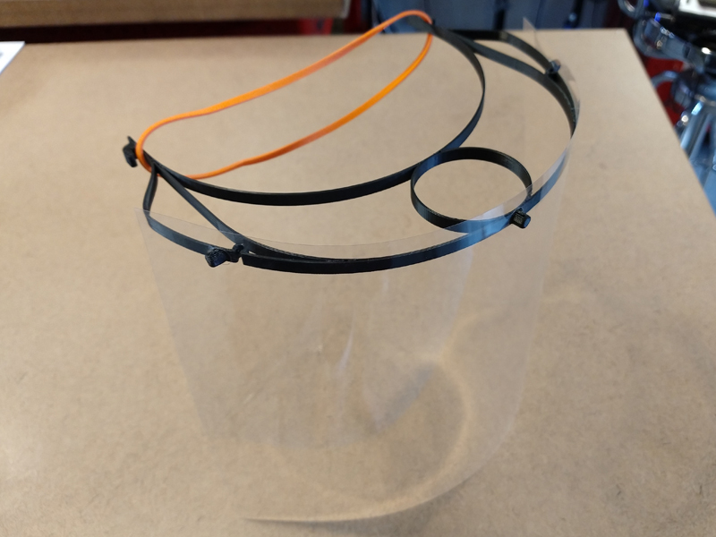
Minimum Viable Product Face Shield v1.0
Minimum Viable Product Face Shield: The goal is to fabricate and get as many Face Shields to hospitals as possible in the least amount of time while still achieving the intended function (Help block bulk aerosol particles from reaching the face). This is achieved with two-fold; the face shield design was paired down and optimized as much as physically possible in order to minimize print time on FDM/PJP/FFF type printers, and the part was printed “stacked” to maximize print density in a 24 hour period. Readily available transparency/report cover film with a standard 3-hole punch pattern and rubber bands comprise the other components of the mask. We are able to output 120 functional face shields, across 2 printers, in a little under 24 hours.
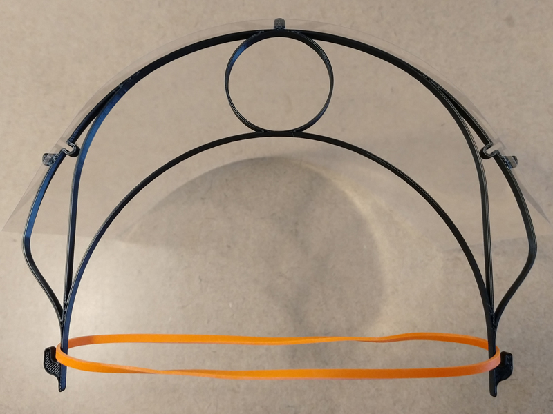
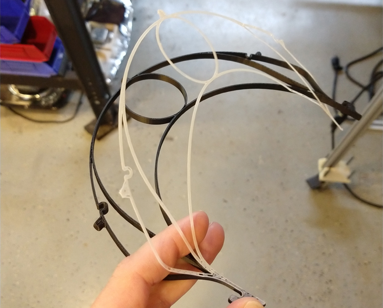
Top Down View of Frame features
Design: The print is optimized for minimizing print time, which generally means less print material is used also. The entire part is two path widths wide, around 1.20mm, except for the 3 pegs and the hook features for the rubber band which are solid. It is 15 layers, at 0.33mm layer height, approximately 5mm high. The pegs are radially spaced at the standard US 4.25 inch 3-hole punch distance. The pegs on the end are spaced slightly further out so as to keep the transparency/report cover face shield taught. There are two built-in spring features at the side pegs, to also help with tension but to take up any extra slack from the ~6-8mm diameter hole range on different US 3-hole punches. Hook features at the back side hold the standard 7″ x 1/8″ rubber bands. You will possibly need to tweak the 1.20mm width for your particular printer to ensure that the two paths that form the structure of the part do touch fully for maximum strength.
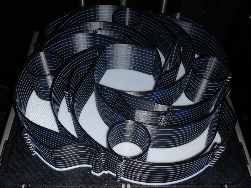
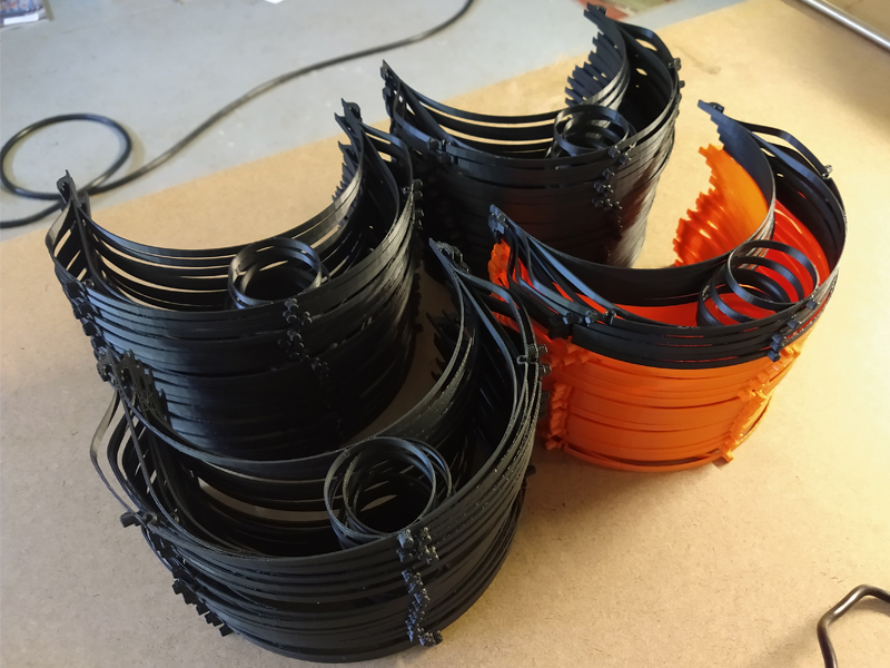
4 X 9 Print Stacking Method
Print Stacking Method: Only 4 frames can be “traditionally” laid out on the print platform by nesting them in X & Y. In order to produce the most amount of parts in the least amount of time, it is not ideal to have to sit by the printer, remove the 4 parts and start another build, as all that time really adds up and is prone to additional errors/issues. The most ideal scenario would be to have full build take a little under 24hrs, and make as many frames as possible in that build, so their is only 1 build per day, significantly reducing build turnaround time and labor.
To achieve this we must stack the frames vertically one on top of another in the Z direction. I modified the physical model to have a single layer of support material (HIPS) in between each (ABS) frame so they separate cleanly. While stacking the parts without any support material in between may be possible, you are much more likely to have these thing parts break when trying to peel them apart (more on that in the next section). You can see the white HIPS support material in between the black ABS frames. With this method, we can print as high as our Z-axis. I am printing 15 frames high, so 4 stacks of 15 yield 60 frames per printer in a little under a 24hr period.
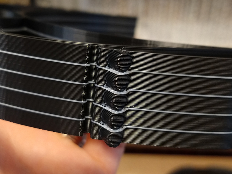
Close-up of Print Stacking
Easy Peeling off Single Support Layers
Dual or Single Extruder Print Stacking Method: While the particular printer I am using (dimension 1200es) has a dual extruder, it is still possible to print stacked with a single extruder with PLA. Rather than the single support material layer being a different material, that layer could be selected as a being compromised as a perforated layer. This layer would be similar of the print process at the top of automatic single material supports with the “support material” option selected in the desktop printer slicer. Since PLA has minimal warp, this perforated layer should allow the stack to print correctly, yet still be separated when the build is complete.
100 Face Shield Frames in ~19 hours
Production Timing: The printer I am using is not particularly super fast, and it takes roughly about ~22 minutes to print one frame. It is very likely that a desktop printer could be tweaked to print much faster than this. I am trying to time it for one ~23hr build per day to minimize turn over time. I can achieve this by printing 15 frames high, so my 4 stacks of 15 yield 60 frames per printer. I am running two of the same printer, so I can output 120 complete Face Shields per day with this frame design and print stacking method.
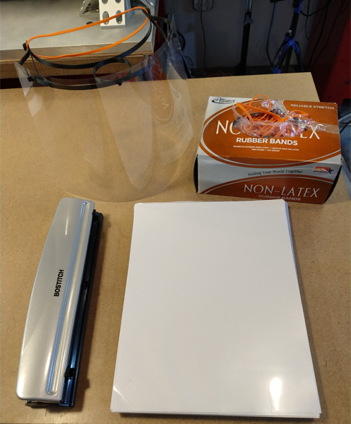
Readily available and Low cost materials
Materials: The goal was minimize any custom parts and use as much readily available parts and materials as possible. Make sure you have the clear face shield aligned straight when you attach it to the frame.
Total cost of materials for each complete assembled Face Shield is around $0.70.
Update 04/01/2020: Based on feedback I have added a top shield piece to protect from falling particles. See image below. Still keep in mind that Face Shields do not take the place of Goggles or safety glasses, they just help block bulk particles. Rather than add a lot of extra print time and make the design a lot less conformable by adding to the frame to cover the top, I opted to add a second simple piece of cut and bent film. This way one can still produce 60+ completely assembled face shields with one printer per day.
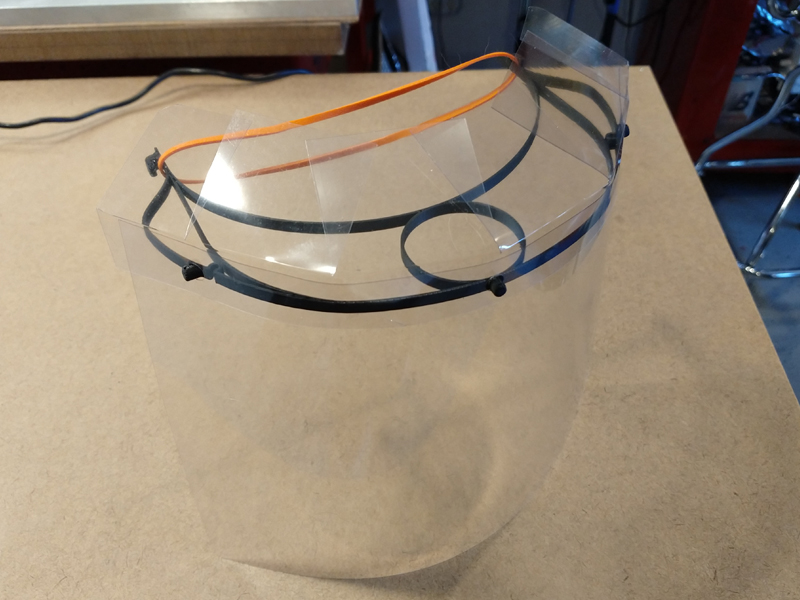
Minimum Viable Product Face Shield v1.1
I have added to the download zip folder a printable 8.5″x11″ PDF template to Cut & Bend the top shield pieces. 3 top covers can be made from a single report cover film sheet as laid out in the PDF. Make sure you print with the “actual size” option selected. These are sized for the report covers (which are slightly over sized), so you will notice the ends are cut off, but you can still easily trace all needed dimensions. Cut on solid lines and bend on dashed lines.
Download All Source Files here: MVP Face Shield v1.1. Contains the Frame and Stacked Assemblies in Source Solidworks 2015, Parasolid, STEP and STL formats.


Great design. Much simpler print than others. What size nozzle are you using?
Thanks,
Darise
Thank you Darise! It was printed with a 0.40mm nozzle orifice size
tried to print this but having problems getting the first layer to stick. Oddly in cura it slices it where it’s dropping material spaced apart? I’m printing it horizontally Here’s a video I took – https://youtu.be/x5EMUUGAL5k
very strange, I have not used Cura before, it is likely that you need to make the actual part model wall thickness a little thicker to accommodate the slicer generating two paths.
Hi — a quick gripe about this design. Using these length of rubber bands, the fit on the head is way too tight and will become severely uncomfortable after 10 minutes. I had to end up snipping the rubber bands and tying each end off to the side hooks. Then, the fit was perfect.
A perfect solution for larger head sizes, thank you Nick
Excellent design! Love how flexible it is and how it molds to the head. I am using rubber bands and an extender to further fit it perfectly to individual head. Thank you for this design!
Thank you Jan!