
Compared with a static cleaning chamber where both the mask and lamp are fixed, I want the mask to rotate in my cleaning chamber as this will ensure there are no shadows and UV-C light can get into every nook and cranny on the masks surface. As an added measure I would also want the mask to change its angle up/down each time it makes a full revolution. This way we can ensure full coverage, reaching every exterior and interior part of the mask surface.
One of my favorite places to look when I need kinematic mechanism inspiration is Nguyen Duc Thang’s youtube channel; thang010146. His channel has been around a long time and is constantly updated with all kinds of kinematic mechanisms that he himself designs and documents. It is really easy to get sucked into watching one video after another in his channel! I really appreciate his work. Looking around, one mechanism really stood out to me that uses a single motor to both rotate and angle an object up and down; check out his “Drawing a spherical helix” video above.
I would need to modify this mechanism because if left as-is, the mask would always follow the same exact helical path (orange line in the video). What I want to do is have a single motor rotate the mask, and then also once per revolution, increment the mask angle down or up in a reciprocating range. That way every up or down angle increment of the mask gets one full rotation in the chamber before changing. This way we are always exposing every little nook and cranny on the mask. So from the video the idea would be to get rid of the big gray gear, and then make the fixed purple gear only have a few teeth so that the yellow gear only turns a little bit with each full rotation of the system. This yellow gear in turn would need to change the angle of the mask.

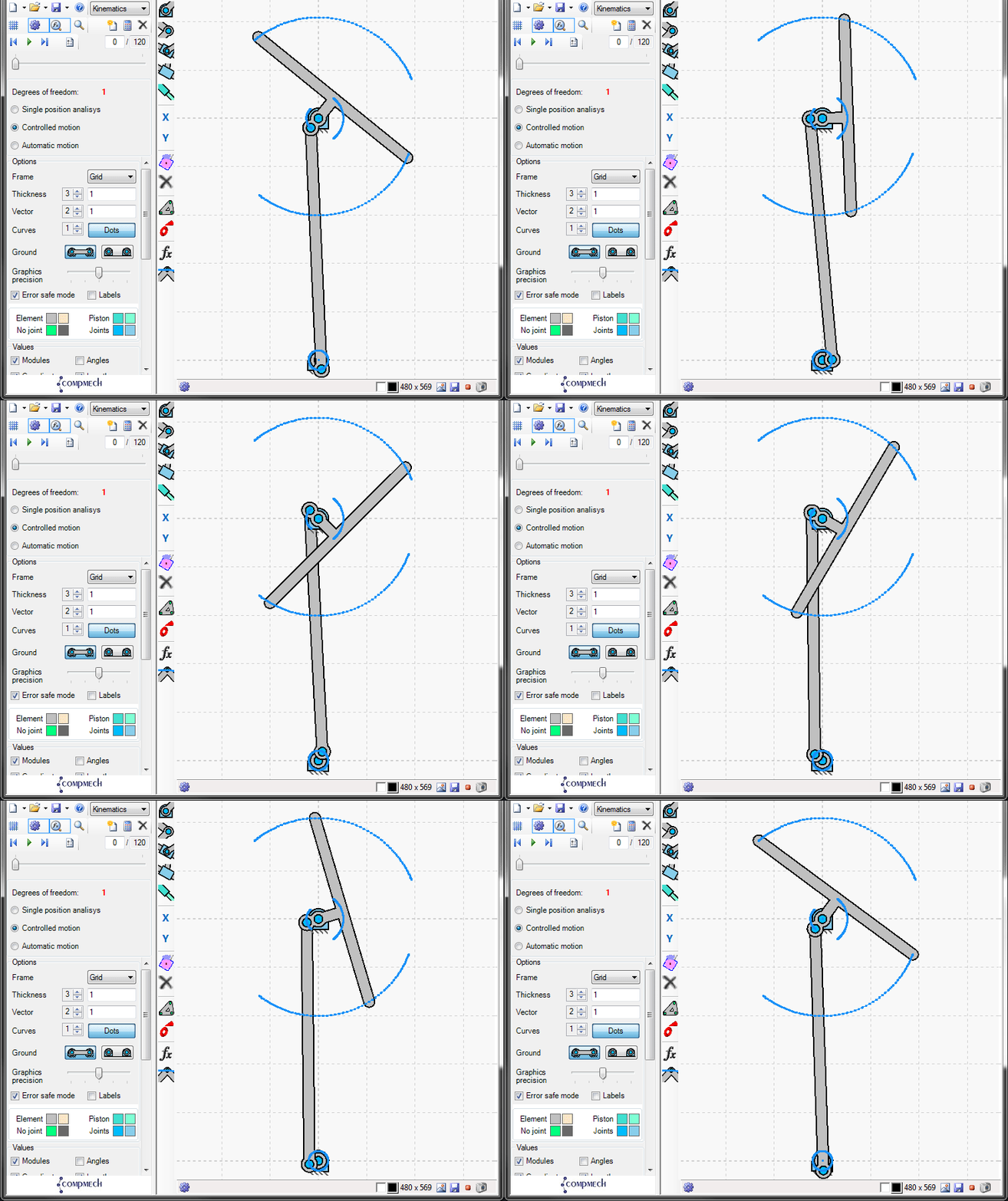
So with this idea, the yellow gear would need to be connected to a reciprocating kinematic linkage. To help play around with different kinematic linkages and sizing I came across a really simple to use program called GIM. GIM allows you to quickly layout and animate different linkage shapes and journal bearing points and then map out the movement of the entire mechanism and target end effector linkage. (Yes this can be done with Soildworks, but this is a faster and simple implementation). The animated gif above shows a side view of the simple linkage I came up with to have small a continuous rotation at the bearing on the bottom cause reciprocating motion of around +50 and -50 degrees which the mask would be attached (large T-shaped bar at the top). That small bearing at the bottom would be the incremental continuous rotation of basically the yellow gear in the youtube video mechanism.

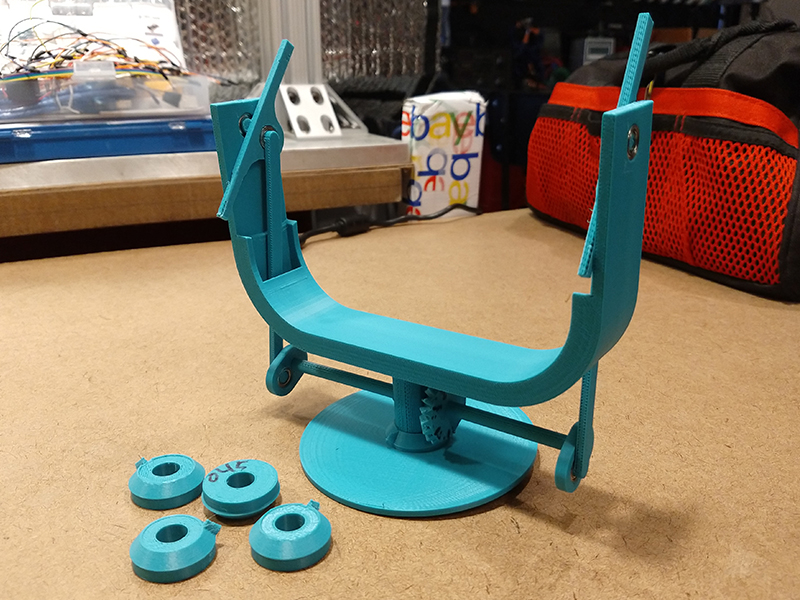
The above image shows the first prototype mechanism. The large circular part at the bottom is fixed and if you look at the center it has a right angle gear with only 1 tooth. So as the big U-shaped part rotates around the fixed circular base, that other fully toothed right angle gear is incremented a little bit. That fully toothed right angle gear is that connected by a small shaft to two linkages (one of each end of the U-shaped part) that I developed in the GIM simulation above. So the angled end parts of that mechanism will connect to the masks somehow (I need to continue to work on this). I tired to put the linkages on the inside of the U-shaped part to try and minimize the width of the rotating section so we can be slightly closer the UV-C source, but I don’t think this will work and it will interfere with however we hold the mask, so I will move it to the outside. Also the little single toothed right angled gears in the bottom right of the image were for getting the fit just right so the linkage mechanism would not rotate on its own when not contacting the single tooth gear. For all the linkages and rotating sections, I used these very compact little 1060 bearings that I have had lying around for a long time.