
The video above shows the partially assembled final version operating. For this test run I have the UV-C bulb power supply turned off, and after pressing the start button I am simulating the lid being closed by holding the safety limit switch with my finger.
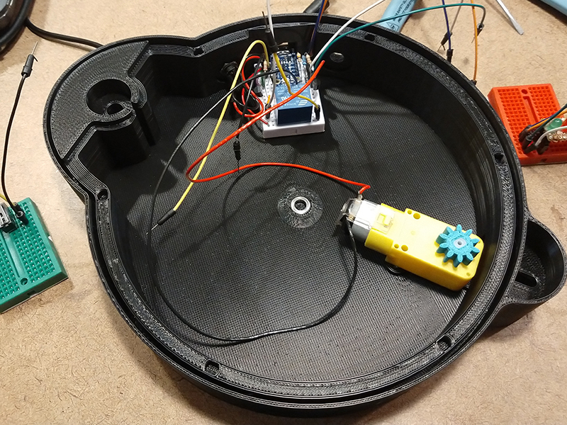
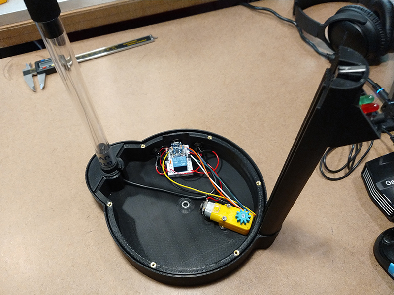
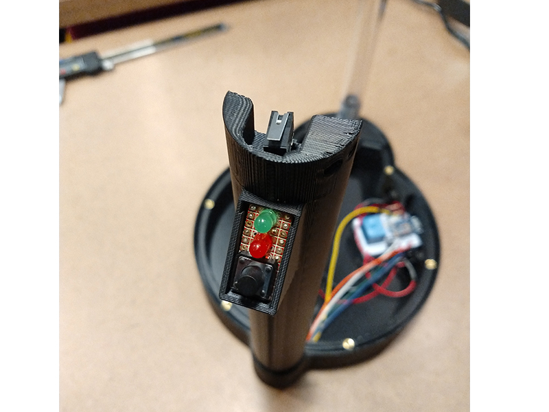
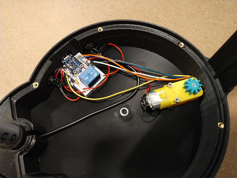
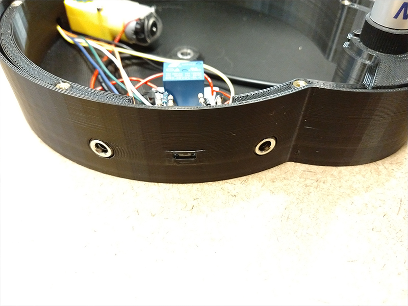
The images above show some of the final assembly of the unit, including wire routing. The wire routing for the daughter board and limit switch in the vertical channel was a little tricky to feed through. As the UV-C bulb is hard wired to its power supply I had to cut and solder on 2.5mm barrel connectors so the power supply could be plugged into the unit and to run the power inside the unit through the relay.
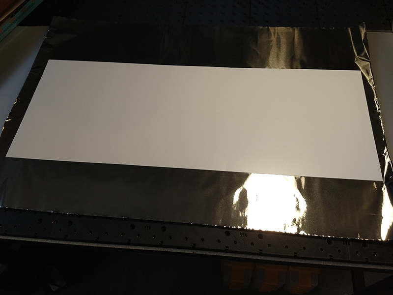
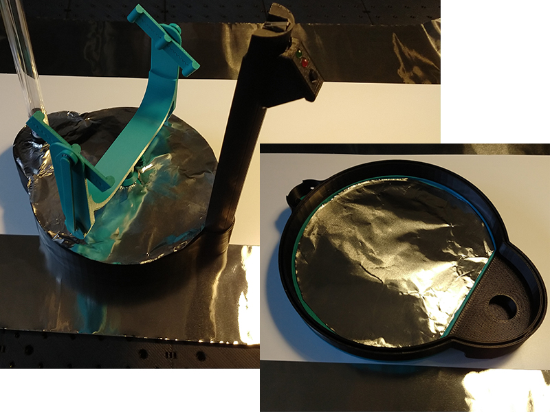
I cut out and attached heavy duty aluminum foil to all interior surfaces with double sided VHB tape. These foil reflectors really help spread the unabsorbed UV-C energy all around the chamber. I measured with my UV-C meter the ambient flux within the chamber/behind the mask to be about 1mW/cm^2. I am also directing more energy directly to the mask surface with the elliptical reflector around the bulb. I am not including this ambient energy and the elliptical reflector concentrations in my calculations for how long it will take to sanitize the masks (See part 3), so this extra unaccounted for energy will serve as my factor of safety.
Programming was fairly straight forward, and yes there is likely a better way to go about this as I am not an programming expert, but this code works correctly as intended. The Arduino code I wrote is shown below. I initially tired to use interrupts and interrupt pins for the safety limit switch but I could not get it to work right so I just made a loop that checks the status of the limit switch every millisecond. You will notice the timer1 amount is not exactly 17 minutes, as the trinket has no RTC (real time clock) so I had a do a few trials to calibrate the timing to an actual 17 minutes.
int greenled = 2;
int motorpin = 0;
int uvcrelay = 4;
int button = 1;
int limsw = 3;

long timer1 = 0;

void setup() {
  // initialize the digital pin as an output.
  pinMode(greenled, OUTPUT);
  pinMode(motorpin, OUTPUT);
  pinMode(uvcrelay, OUTPUT);
  pinMode(button, INPUT);
  pinMode(limsw, INPUT);
}

void loop() {
      if (digitalRead(button) == LOW && digitalRead(limsw) == LOW) {
            digitalWrite(greenled, LOW);
            analogWrite(motorpin, 255);
            delay(20);
            while (digitalRead(limsw) == LOW && timer1 < 977260) {
              digitalWrite(uvcrelay, HIGH);
              analogWrite(motorpin, 100);
              delay(1);
              timer1++;
            }
            if (timer1 = 977260){
              analogWrite(motorpin, 0);
              digitalWrite(greenled, HIGH);
              digitalWrite(uvcrelay, LOW);
              timer1 = 0;
            }
            else {
              analogWrite(motorpin, 0);
              digitalWrite(greenled, LOW);
              digitalWrite(uvcrelay, LOW);
              timer1 = 0;
            }
           }
        if (digitalRead(button) == LOW && digitalRead(limsw) == HIGH) {
          digitalWrite(greenled, HIGH);
          delay(50);
          digitalWrite(greenled, LOW);
          delay(50);
          digitalWrite(greenled, HIGH);
          delay(50);
          digitalWrite(greenled, LOW);
      }
      if (digitalRead(limsw) == HIGH && timer1 == 0) {
         digitalWrite(greenled, LOW);
      }
}