
The above video shows the next version of the mask rotation and tilting mechanism fully operational. I moved the linkages to the outside of the U-shaped rotation mechanism. The U-shaped rotation part is connected to a big internal tooth gear inside the base (basically the diameter of the base). the TT motor drives this big gear with smallest pinion gear possible so to show the entire mechanism down further. In the video I am running the motor at 3.3V, but I can slow it down a bit by running at 2V and it still operates.
With each full rotation the single tooth gear fixed to the base moves its mating fully toothed gear by 3 teeth, which through the reciprocating mechanism, tilts mask tilts up or down about ~10-30 degrees depending on the mask position. The fully toothed gear has 20 positions, but as we are moving an odd amount of teeth each time, we skip around in tilt angle positions, but we do reach all of the angle positions, thought not in order, which probably is good to jump around.

To hold the masks in place to the tilt mechanism, I did not want to have to physically attach to the masks themselves as that would block some of the filter area, even if only a little bit. So instead we attach a small amount of the straps to the tilt mechanism. The above image shows two part magnetic clip that clamps the mask straps in place. Both parts are toothed so the straps can be gripped, and each half has embedded magnets with enough force to hold everything in place but easy enough to pull apart. You just have to take care to make sure the straps are at least semi-taught so the mask correctly moves with the change in tilt angle.
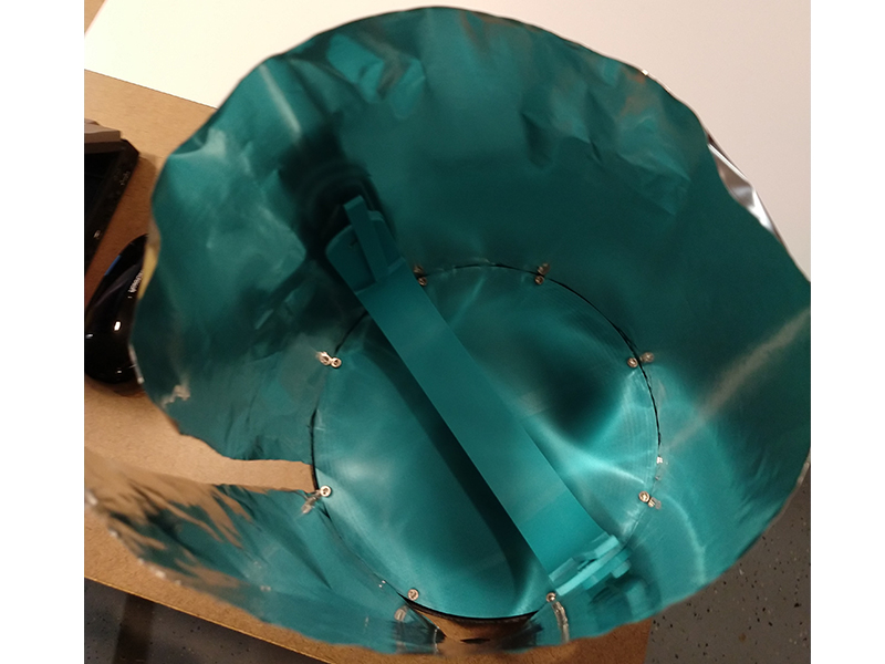
All along the outside edge of the black base, between the large round teal part, there is actually a small gap so a flat plastic sheet material (~0.5mm) can be inserted to form the walls of the chamber. This will take much less time to produce and be will lower cost compared with printing all of the chamber walls. I also can sandwich in aluminum foil so the UV-C rays can reflect all over the chamber too. Image above shows me quickly mocking the up to see and i looks like it will work out quite well.

For the next iteration of the design, I will need to add where the aquarium UV-C bulb will mount. This will be just outside the the turn radius of the mask rotation mechanism so we get it as close to the mask surface as possible. Since the bulb is basically just a quartz tube, it will just sit in a circular pocket in the top of the base. But I will also make the shape of the base around the bulb, and thus the chamber plastic sheet walls/aluminum reflector, to form an elliptical reflector so I can try and focus more of the bulb energy directly to the mask. See the diagram above for the difference between ray paths for elliptical and parabolic reflectors.
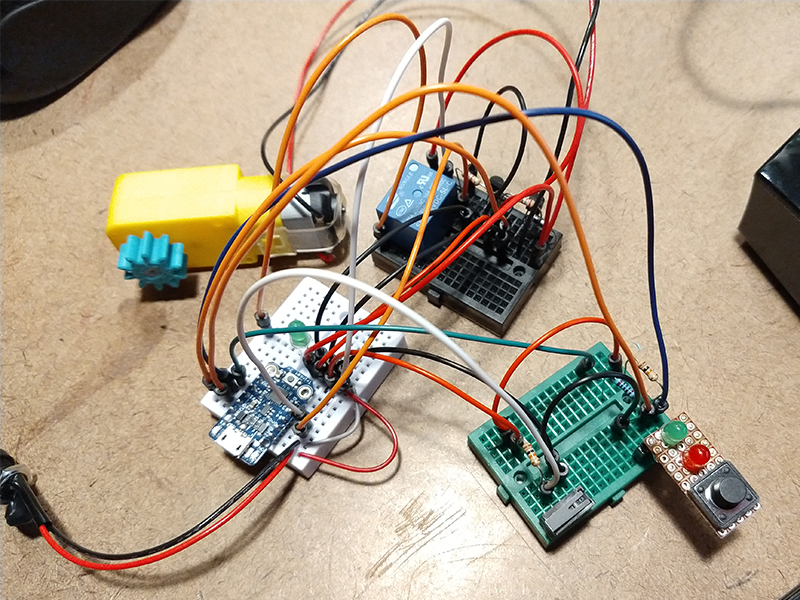
The above image is the initial prototype layout of the electronics for the sanitizing chamber. There are probably different and better ways to implement this, but since I am not an electronics expert and for this first version this is plenty sufficient to prove out the concept. I am using all components that I had on hand already for ease of prototyping (except of course the Aquarium UV-C Bulb).
I am using a 3.3v Adafruit Trinket as the micro controller and using all 5 of its pins. A 3.3v wall power supply will drive the microcontroller, motor, relay and leds, etc. This is actually a little lower than what is recommended (4.5v) for the 3.3v trinket version but seems to work fine. The low pressure mercury vapor UV-C Aquarium bulb has its own little power supply rated at 24-36V, which I am assuming a range is listed because it’ll draw differently at startup than when already ignited. Ideally of course one would certainly only want a single power supply for a product, but for ease of integration and quick implementation for now, this the bulb power will be a separate subsystem turned on/off by the relay. So the bottom of the cleaning chamber will have 3 plug ports: 3.3v, Aquarium bulb power supply and the trinket usb micro so I can tweak the code.
For safety, I do not want a user to be able to see the UV-C light while it is running if they were to open the lid, so I am adding a little limit switch so the system knows that the lid is closed (laid out here on the green breadboard). If the lid is opened the system will immediately stop everything and turn the UV-C bulb off via the relay.
The motor to drive the mask rotation system is a common hobby “TT Motor”. I wanted a gear motor to have enough torque and also to make all the mask rotation be as slow as possible. I would prefer to use something like an N20 gear motor as they come in a range of gear ratios but they are actually kind of expensive in small quantities. So, This 1:120 “TT” gear motor is readily available and can run at 3V. I am using a transistor with it so I can pwm’d down as slow as possible while still being able to drive everything.
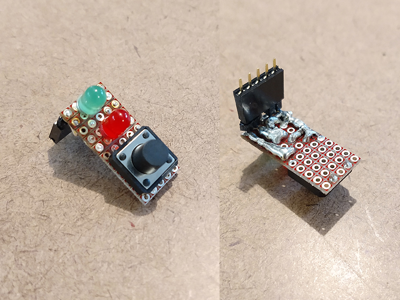
The above image shows the little daughter board for the main user control interface which will be located near the top of the machine, separate from the main board. The plan is when the top door is closed (checked via limit switch) and the user presses the button, the red light is on during the sanitizing cycle. One the the cycle is complete, the green light stays on until the door is opened. If the door is open and the user presses the start button, the green light will flash (signifying an error). Since there are only 5 pins on a trinket, I have run out, so the Red LED is actually inline with the motor pin, which works because the motor is only turning when it is sanitizing. The solder joints/traces on the back side are pretty crude, but they get the job done.
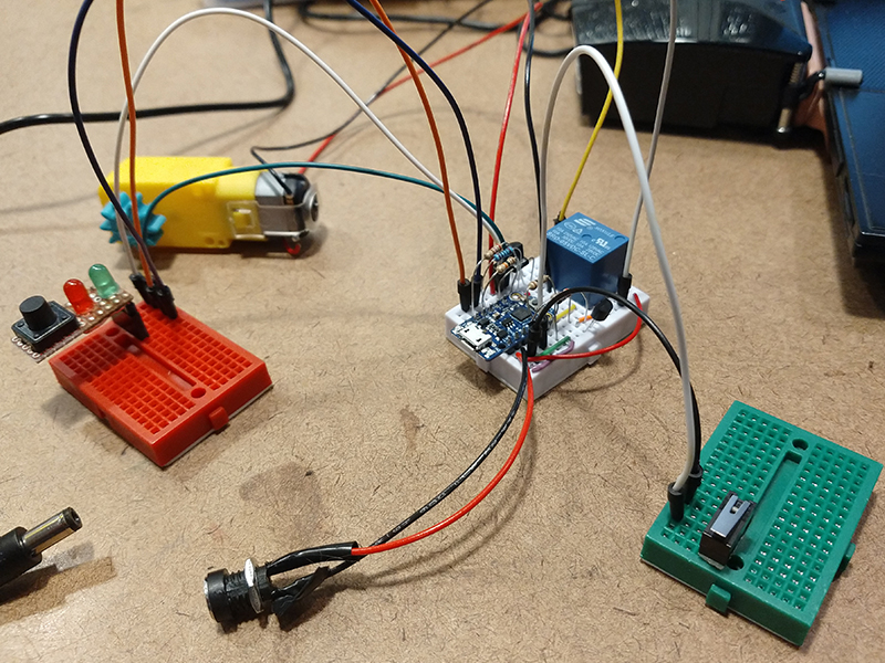
The above image shows the much cleaned up and refined electronics. I was able to squeeze all of the wires and components on to the single white breadboard. This breadboard will be actually be somewhere in the bottom section of the cleaning chamber (not in the actual UV-C illuminated part). The green and red breadboards are just place holders to represent that there will be a cable harness connecting to the daughter control board and a cable harness connecting to the safety limit switch for the lid.
I am using a 3.3v Adafruit Trinket for the microcontroller as I had it on hand already. I really like the Trinket platform as they are just so very small, easy to use, Arduino compatible and I have used them on a ton on other product prototyping projects before with great success/integration. I actually really wanted to try out the newer and more powerful M0 Trinket version but unfortunately they have been sold out for quite some time. I also leaned of the Seeeduino XIAO recently, which looks very interesting too, as it is very small as well, but offers even more I/O pins and a low cost.
Compared with a static cleaning chamber where both the mask and lamp are fixed, I want the mask to rotate in my cleaning chamber as this will ensure there are no shadows and UV-C light can get into every nook and cranny on the masks surface. As an added measure I would also want the mask to change its angle up/down each time it makes a full revolution. This way we can ensure full coverage, reaching every exterior and interior part of the mask surface.
One of my favorite places to look when I need kinematic mechanism inspiration is Nguyen Duc Thang’s youtube channel; thang010146. His channel has been around a long time and is constantly updated with all kinds of kinematic mechanisms that he himself designs and documents. It is really easy to get sucked into watching one video after another in his channel! I really appreciate his work. Looking around, one mechanism really stood out to me that uses a single motor to both rotate and angle an object up and down; check out his “Drawing a spherical helix” video above.
I would need to modify this mechanism because if left as-is, the mask would always follow the same exact helical path (orange line in the video). What I want to do is have a single motor rotate the mask, and then also once per revolution, increment the mask angle down or up in a reciprocating range. That way every up or down angle increment of the mask gets one full rotation in the chamber before changing. This way we are always exposing every little nook and cranny on the mask. So from the video the idea would be to get rid of the big gray gear, and then make the fixed purple gear only have a few teeth so that the yellow gear only turns a little bit with each full rotation of the system. This yellow gear in turn would need to change the angle of the mask.
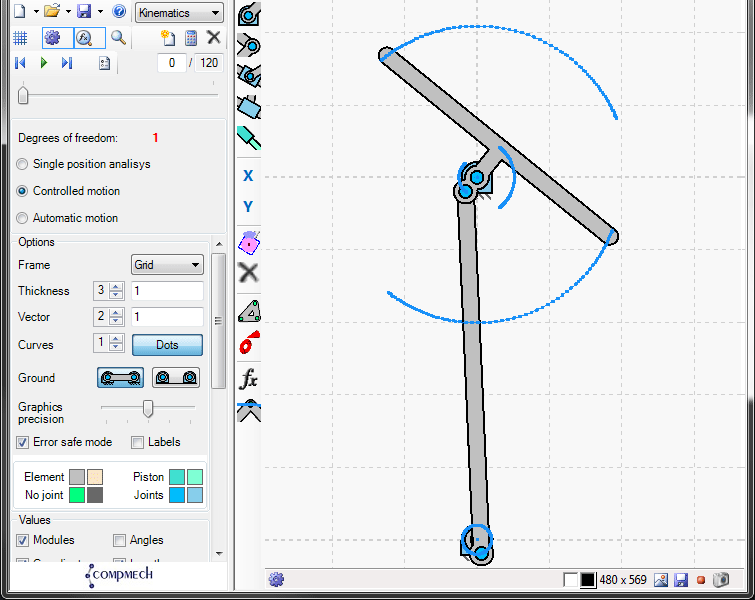
So with this idea, the yellow gear would need to be connected to a reciprocating kinematic linkage. To help play around with different kinematic linkages and sizing I came across a really simple to use program called GIM. GIM allows you to quickly layout and animate different linkage shapes and journal bearing points and then map out the movement of the entire mechanism and target end effector linkage. (Yes this can be done with Soildworks, but this is a faster and simple implementation). The animated gif above shows a side view of the simple linkage I came up with to have small a continuous rotation at the bearing on the bottom cause reciprocating motion of around +50 and -50 degrees which the mask would be attached (large T-shaped bar at the top). That small bearing at the bottom would be the incremental continuous rotation of basically the yellow gear in the youtube video mechanism.
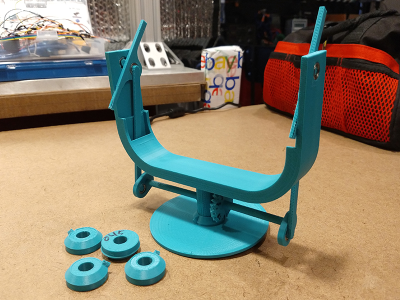
The above image shows the first prototype mechanism. The large circular part at the bottom is fixed and if you look at the center it has a right angle gear with only 1 tooth. So as the big U-shaped part rotates around the fixed circular base, that other fully toothed right angle gear is incremented a little bit. That fully toothed right angle gear is that connected by a small shaft to two linkages (one of each end of the U-shaped part) that I developed in the GIM simulation above. So the angled end parts of that mechanism will connect to the masks somehow (I need to continue to work on this). I tired to put the linkages on the inside of the U-shaped part to try and minimize the width of the rotating section so we can be slightly closer the UV-C source, but I don’t think this will work and it will interfere with however we hold the mask, so I will move it to the outside. Also the little single toothed right angled gears in the bottom right of the image were for getting the fit just right so the linkage mechanism would not rotate on its own when not contacting the single tooth gear. For all the linkages and rotating sections, I used these very compact little 1060 bearings that I have had lying around for a long time.