
Be sure to also check out Parts One, Two, Three, Four, Five, Six, Seven & Eight for lots of details on how this was developed!
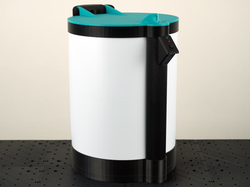
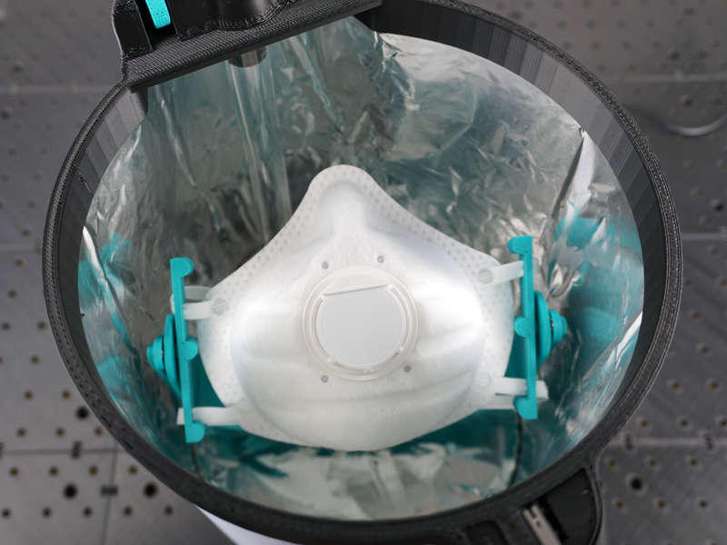
The video above demonstrates the fully functional UV-C Sanitizing Chamber. The system is able to fully sanitize a disposable N95 face mask in just 17 minutes in order to prolong its usable life. In those 17 minutes, it applies a little over 1.0 J/cm^2 of UV-C radiant flux across the front and inside surfaces of the N95 face mask by continuously rotating and tilting the mask up and down in front of a Low pressure Mercury Vapor UV-C Lamp. I estimate the cost to build this sanitizing chamber currently to be around $60 USD.
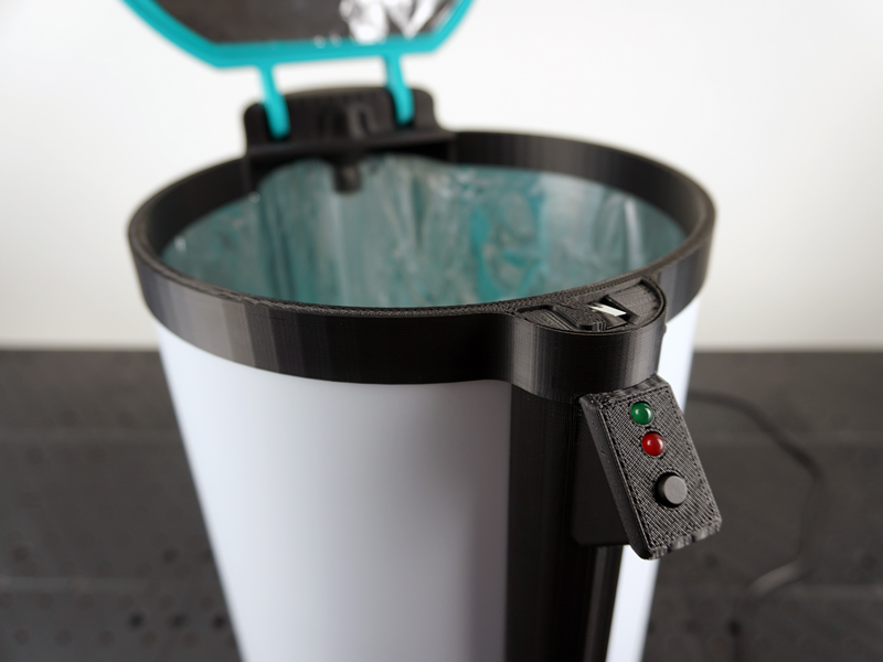
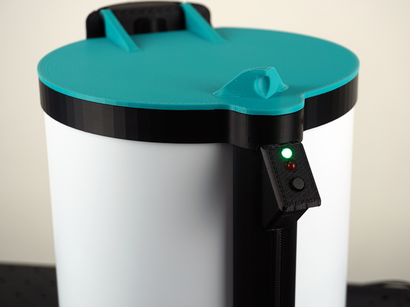
Functions of the system demonstrated in the video include, Green LED flashing warning and not starting if the start button is pressed and the lid is not closed, pressing the start button with the lid closed starts the sanitizing process and indicated this by turning on the red LED, and stopping the system and turning off the UV-C bulb if the lid is open wile it is sanitizing. NOTE: For the second scene of the video, I am manually defeating the safety limit switch by holding it down while the lid is open, only to demonstrate the UV-C bulb and Mask rotation mechanism in motion.

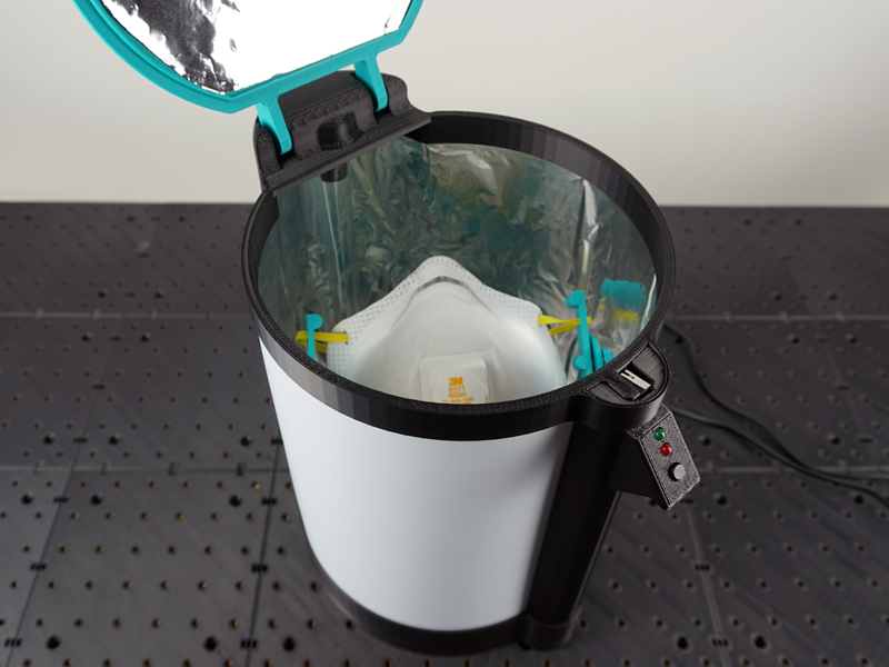
The video above shows the partially assembled final version operating. For this test run I have the UV-C bulb power supply turned off, and after pressing the start button I am simulating the lid being closed by holding the safety limit switch with my finger.
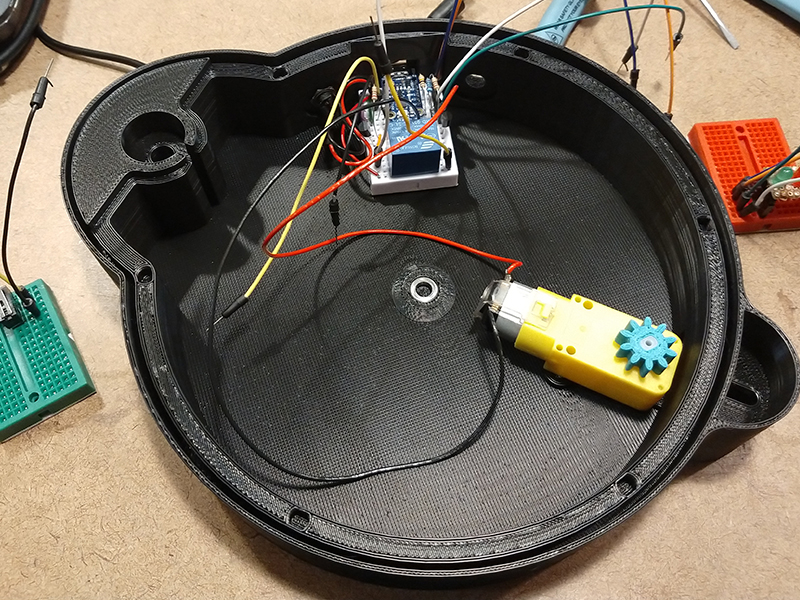
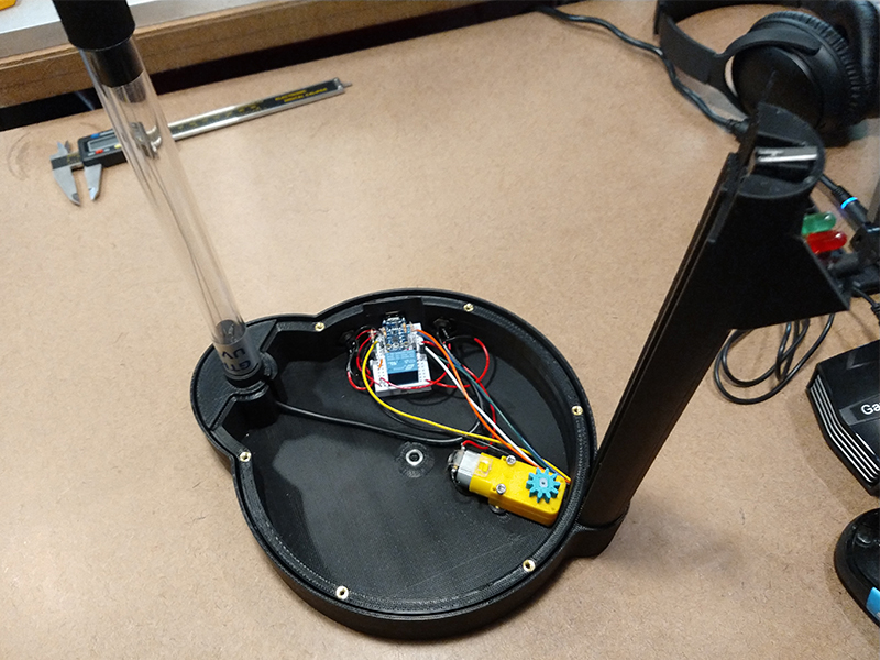
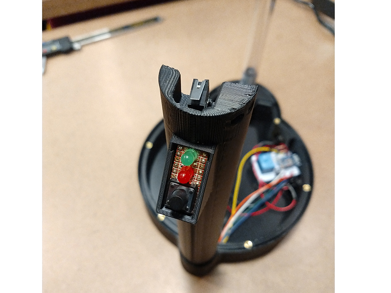
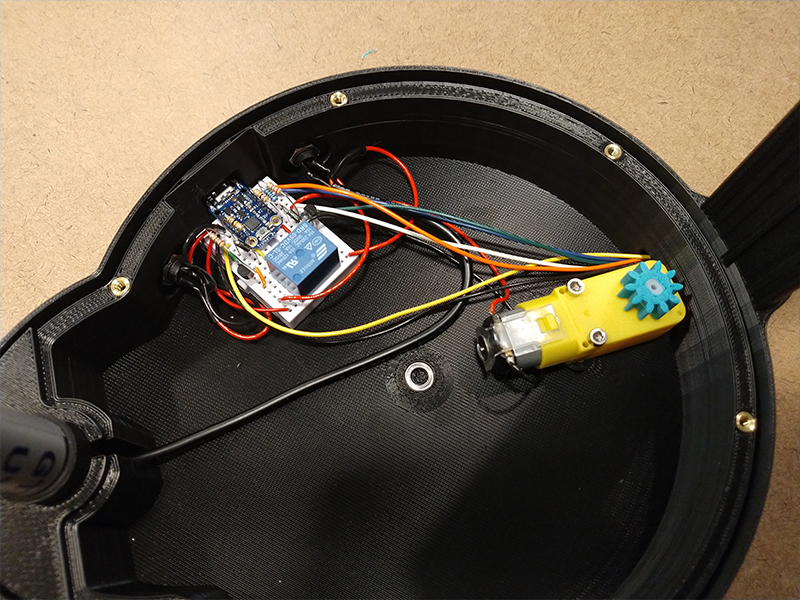
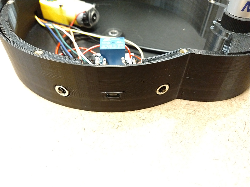
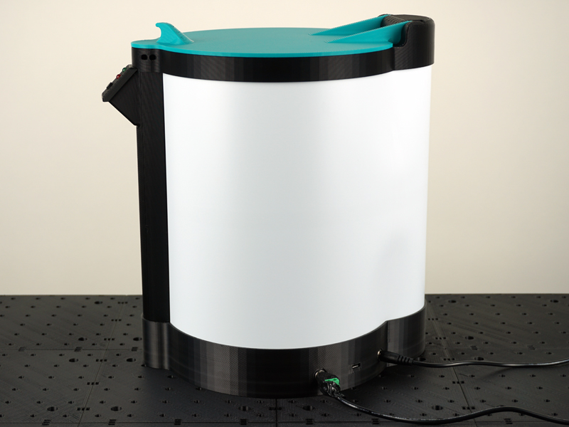
The images above show some of the final assembly of the unit, including wire routing. The wire routing for the daughter board and limit switch in the vertical channel was a little tricky to feed through. As the UV-C bulb is hard wired to its power supply I had to cut and solder on 2.5mm barrel connectors so the power supply could be plugged into the unit and to run the power inside the unit through the relay.
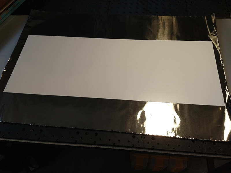
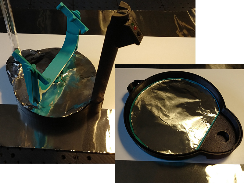
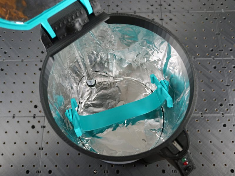
I cut out and attached heavy duty aluminum foil to all interior surfaces with double sided VHB tape. These foil reflectors really help spread the unabsorbed UV-C energy all around the chamber. I measured with my UV-C meter the ambient flux within the chamber/behind the mask to be about 1mW/cm^2. I am also directing more energy directly to the mask surface with the elliptical reflector around the bulb. I am not including this ambient energy and the elliptical reflector concentrations in my calculations for how long it will take to sanitize the masks (See part 3), so this extra unaccounted for energy will serve as my factor of safety.
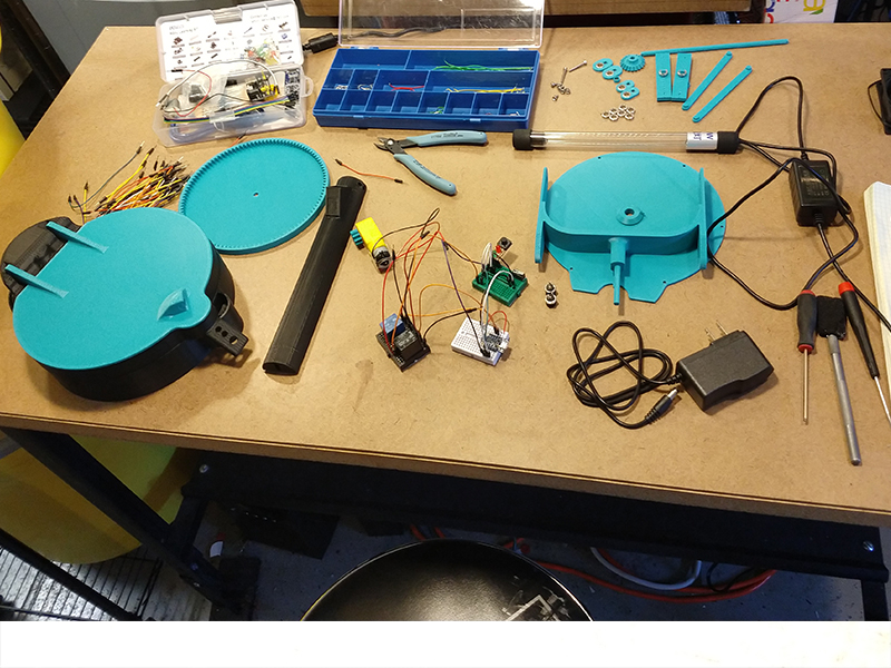
Programming was fairly straight forward, and yes there is likely a better way to go about this as I am not an programming expert, but this code works correctly as intended. The Arduino code I wrote is shown below. I initially tired to use interrupts and interrupt pins for the safety limit switch but I could not get it to work right so I just made a loop that checks the status of the limit switch every millisecond. You will notice the timer1 amount is not exactly 17 minutes, as the trinket has no RTC (real time clock) so I had a do a few trials to calibrate the timing to an actual 17 minutes.
int greenled = 2;
int motorpin = 0;
int uvcrelay = 4;
int button = 1;
int limsw = 3;

long timer1 = 0;

void setup() {
  // initialize the digital pin as an output.
  pinMode(greenled, OUTPUT);
  pinMode(motorpin, OUTPUT);
  pinMode(uvcrelay, OUTPUT);
  pinMode(button, INPUT);
  pinMode(limsw, INPUT);
}

void loop() {
      if (digitalRead(button) == LOW && digitalRead(limsw) == LOW) {
            digitalWrite(greenled, LOW);
            analogWrite(motorpin, 255);
            delay(20);
            while (digitalRead(limsw) == LOW && timer1 < 977260) {
              digitalWrite(uvcrelay, HIGH);
              analogWrite(motorpin, 100);
              delay(1);
              timer1++;
            }
            if (timer1 = 977260){
              analogWrite(motorpin, 0);
              digitalWrite(greenled, HIGH);
              digitalWrite(uvcrelay, LOW);
              timer1 = 0;
            }
            else {
              analogWrite(motorpin, 0);
              digitalWrite(greenled, LOW);
              digitalWrite(uvcrelay, LOW);
              timer1 = 0;
            }
           }
        if (digitalRead(button) == LOW && digitalRead(limsw) == HIGH) {
          digitalWrite(greenled, HIGH);
          delay(50);
          digitalWrite(greenled, LOW);
          delay(50);
          digitalWrite(greenled, HIGH);
          delay(50);
          digitalWrite(greenled, LOW);
      }
      if (digitalRead(limsw) == HIGH && timer1 == 0) {
         digitalWrite(greenled, LOW);
      }
}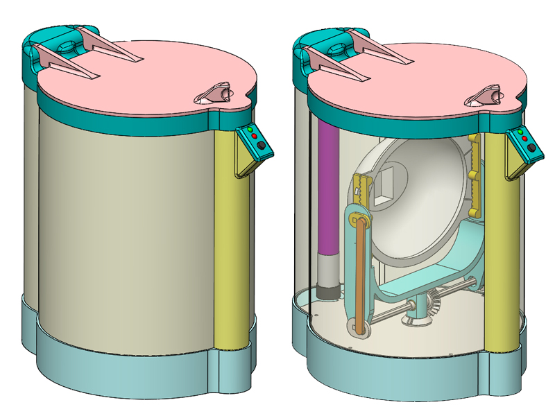
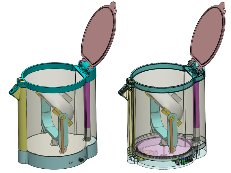
the images above show the final CAD model of the unit. Over all dimensions are 198mm [7.8″] wide, 275mm [10.8″] deep and 287mm [11.3″] high. The walls of the chamber are made of a single piece of 0.5mm PS sheet that I had leftover from another project. The sheet is held in place by being fit in the slots in the base (light Teal) and top frame (Dark Teal). All internal surfaces will be lined with aluminum foil to help reflect the light all around. The design uses only a few screws with the rest of the parts nesting or being press fit into each other. You can see the user control panel with its green & red LEDs and black button, at the top of the unit near the opening lid (light red). The height and diameter of the chamber were sized to accommodate the four N95 masks that I modeled, while still getting the masks as close to the UV-C bulb as possible. It should also be possible to fit many other disposable N95 masks types in here as well.
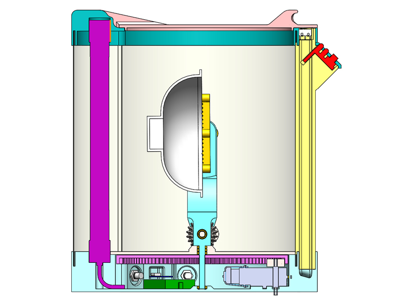
The above image shows the cross section view of the unit. You can see how the UV-C lamp and the vertical channel (light yellow) are captured between the top frame and base. The vertical channel has a hollow opening inside of it to run the wires for the daughter control board and the safety limit switch down to the main control breadboard (green) in the base. The light purple part is the big internal tooth gear that is pressed onto the U-shaped rotating part shaft (light teal, center). I added flats to any shafts that have gears pressed on them so there is no chance of anything slipping. The gray TT motor in the bottom right has a small pinion gear on its top shaft which mates to in the internal gear teeth. Again all joints and rotating parts use small 1060 bearings.
In the above image I made a number of the parts transparent for clarity. You can see the elliptical reflector shape around the UV-C lamp which helps to try and reflect some of the extra light on the bulb backside around directly to the mask. On the bottom back side of the unit, you can see the two DC barrel jack plugs and the trinket usb micro connector port. As the unit will be fairly light, the large Lid has hard stops (as shown) to prevent shifting the center of gravity and tipping the unit over, while still providing access to the mask.